Procedure
This guide walks you through the required steps needed to install an 8860 keypad. They are:
-
Update the panel firmware.
-
Program the panel.
-
Install the keypad.
-
Connect to network.
-
Update the keypad firmware.
-
Program the keypad.
Update the Panel Firmware
To use the most up to date keypad features available, update your panel to the latest firmware version. Refer to the table below for keypad features and their corresponding panel firmware versions.
Follow the steps below to update your panel firmware remotely from Dealer Admin:
-
Navigate to Dealer Admin.
-
Select the customer and system.
-
In the menu, click System Remote Update.
-
If you want to view the update details before updating, click the PDF icon next to View Release Notes.
-
Click Update System. If you go to a different page, the system continues to update in the background.
-
After the system has updated, the Panel Name, Firmware Version, and Date Code updates at the top of the page.
|
Feature |
XTL Series |
XT30/XT50 |
XT75 |
XR Series |
|---|---|---|---|---|
|
|
|
|
|
|
|
|
|
|
|
|
|
|
|
Program the Panel
Program the keypad in the panel as a device. To access the Programmer menu, reset the panel by shorting the RESET header, press Keypad in the Carousel menu, enter 6653 (PROG), then press CMD. After completing each of the following steps, press CMD to advance to the next option. To exit the Programmer menu, select CMD to advance through the menu items until you reach STOP at the end of the menu. Select STOP to return to the main screen. Refer to the panel programming guide as needed.
Device Setup
XR and XT75
|
DEVICE SETUP |
|---|
Device Setup
Advance to DEVICE SETUP, then press a select area to enter the setup menu.
|
DEVICE SETUP
|
|---|
Device Number
Set the keypad address.
|
Panel Model |
Available Device Number Range (Keypad Bus) |
|---|---|
|
XR550 |
1-16 |
|
XR150 |
1-8 |
|
XT75 |
1-8 |
|
DEVICE SETUP
|
|---|
Device Name
Enter a name for the device.
|
DEVICE SETUP
|
|---|
Device Type
Select the KEYPAD device type.
|
DEVICE SETUP
|
|---|
Communication Type
For use as a Wi-Fi keypad, select KEYPAD.
XT30/XT50 and XTL Series
|
DEVICE SETUP |
|---|
Device Setup
Advance to Device Setup, then press a select area to enter the setup menu.
|
DEVICE SETUP
|
|---|
Device Number
Set the keypad address.
|
Panel Model |
Available Device Number Range (Network Connection including Wi-Fi) |
|---|---|
|
XT30/XT50 |
1-8 |
|
XTLplus |
0 |
|
XTLtouch |
0 |
|
DEVICE SETUP
|
|---|
Device Name
Enter a name for the device.
|
DEVICE SETUP
|
|---|
Door Device Type
Select NO at Door Device Type
|
DEVICE SETUP
|
|---|
Communication Type
For use as a standard keypad, select NO.
Install the Keypad
Power the Keypad
Caution: Disconnect all power before wiring. Failure to do so may result in equipment damage or injury. Observe polarity when making power connections.
-
Run wire from the power source to the keypad mounting location. See Keypad Bus Wiring Specifications for maximum wire runs.
-
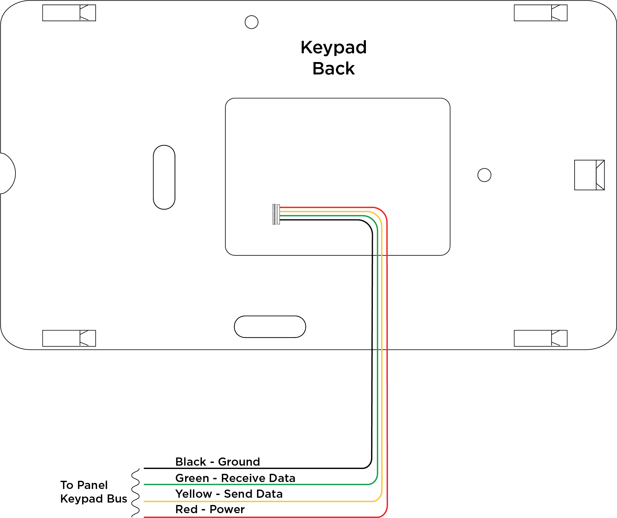
Connect to the PANEL header on the back of the 8860 keypad.
-
Route the keypad wires through the cutouts in the base. See the table to the right.
-
Connect the red wire to panel terminal 7.
-
Connect the yellow wire to panel terminal 8.
-
Connect the green wire to panel terminal 9.
-
Connect the black wire to panel terminal 10.
|
Wire Color |
Purpose |
|---|---|
|
Red |
Power from Panel or Auxiliary Power Source* |
|
Yellow |
Send Data from Panel* |
|
Green |
Receive Data from Panel* |
|
Black |
Ground from Panel* |
*Required Connections
Note: Excluding other Keypad Bus devices, XR panels can supply power for four 8860 keypads, XT30/XT50 panels can supply power for one 8860 keypad, and XT75 panels can supply power for five 8860 keypads. Additional keypads or devices require an external power supply.
Mount the Keypad
To learn more about customization of the 7-Inch Touchscreen Keypad and related items available for order, see Ordering Information.
Wall Mounting
-
Use the keypad base to mark the holes for the screws on the mounting surface. The base should be placed at standing height and the hooks on the base should be facing up.
-
Set the base aside and drill the holes.
-
Use the included screws to secure the keypad base to the surface. Do not overtighten.
-
Attach the wire harness to the keypad.
-
Ensure the on-board camera is on the left. Slide the keypad onto the base and press the keypad into place.
Note: Once you have mounted the keypad, remove the plastic film on the screen. Failure to do so affects the touch functionality of the keypad.
Desk Stand Mounting
Insert one leg into the desk stand holes on the back of the keypad. Slide the leg upwards until the leg firmly snaps into place. Repeat the process to attach the second leg.
.png?cb=e5c4d64ee0e719d2b3e0a0e2aef83130)
Connect to Network
Though not required to communicate with the panel, the keypad needs to be connected to the network to access all 8860 features, including remote updates, video system integration, personalized logos, and image capture when arming and disarming at the keypad. To use the most up to date keypad features available, connect the keypad to hardwired network and update to the latest firmware version.
Connect the Keypad to Wi-Fi
-
Select Options from the Carousel menu.
-
Select Wi-Fi Settings.
-
Select the Wi-Fi network you would like to connect to.
-
Enter the password and select CMD.
Update the Keypad
You can also view How to Update Your 7-Inch Keypad for more information.
Update the Keypad Locally
-
Connect the keypad to the Wi-Fi network before proceeding.
-
Select Options from the Carousel menu, then select Installer Options.
-
Enter 3577 and enter CMD. Select Check for Updates. Follow the on-screen prompts to complete update.
Update the Keypad from Dealer Admin
-
Connect the keypad to the Wi-Fi network before proceeding.
-
Ensure the keypad is programmed as a Keypad device in Device Setup.
-
Navigate to Dealer Admin.
-
Select the Customer and then select the System.
-
On the left menu, select System Remote Update.
-
Click Update next to the keypad.
Note: If the keypad does not show on System Remote Update, ensure it is programmed in Device Setup as a Keypad, not a Door.
Program the Keypad
To program the keypad, enter Options in the Carousel Menu. Select Installer Options, enter
3577 (INST), then press CMD. Select Panel Communications. Select Keypad Bus.
Enter the Keypad Address. It should match the Device Number set in Program the Panel.