

Procedure
-
Check the Panel Firmware
-
Program the Panel
-
Power the Keypad
-
Mount the Keypad
-
Connect to Network
-
Program the Keypad
-
Update the Keypad Firmware
1. Check the Panel Firmware
To use the most up to date keypad features available, ensure your panel has been updated to the latest firmware version.
Select your panel model to view the firmware requirements for specific features.
Note: The XTLplus and XTLtouch do not support Keypad Bus communication.
|
Feature |
Firmware Requirement |
|---|---|
|
|
|
|
|
|
|
Feature |
Firmware Requirement |
|---|---|
|
|
|
|
|
|
|
Feature |
Firmware Requirement |
|
|
|
|
|
|
2. Program the Panel
To allow the control panel to recognize and communicate with the keypad, program the keypad as a device in the panel Programmer Menu.
Follow the instructions for your specific panel model below. After completing each of the step, press CMD to advance to the next option. Refer to the panel programming guide as needed.
XR150/XR550
XT75
XT30/XT50
3. Power the Keypad
Caution: Disconnect all power before wiring. Failure to do so may result in equipment damage or injury. Observe polarity when making power connections.
The keypad receives both power and data from the panel through the keypad bus connection. Using the included 4-wire harness, complete the following steps:
-
Run 18 or 22‑gauge unshielded wire from the power source to the keypad mounting location. See Reference: Keypad Bus Wiring Specification for maximum wire runs.
-
Refer to the following table as you connect the wires to the power source:
-
Connect the red wire to panel terminal 7.
-
Connect the yellow wire to panel terminal 8.
-
Connect the green wire to panel terminal 9.
-
Connect the black wire to panel terminal 10.
-
-
Plug the power source into an unswitched outlet.
-
Route the keypad wires through the cutouts in the base. Connect the harness to the PANEL header when accessible during the mounting process. If the harness must be disconnected for mounting, reconnect it after the keypad is secured.
|
Harness Wire |
Terminal |
Purpose |
|---|---|---|
|
Red |
Panel Terminal 7 |
Power (+12 VDC) |
|
Yellow |
Panel Terminal 8 |
Send Data |
|
Green |
Panel Terminal 9 |
Receive Data |
|
Black |
Panel Terminal 10 |
Ground |
4. Mount the Keypad
Mount the 8863 using the included mounting plate or an optional desk stand. The keypad is compatible with the standard mounting plate, desk stand, and the 8863-BACKUP mounting plate or desk stand configuration when a backup battery is installed. To learn more about customization of the 7-Inch Touchscreen Keypad and related items available for order, see Ordering Information.
Note: Regardless of method, ensure you remove the protective plastic film from the screen after installation to help ensure proper keypad operation.
Optional Backup Battery
The 8863 can be equipped with an optional standby backup battery using the 8863-BACKUP kit. The kit includes a standby battery and a battery case with a breakaway wall tamper. The battery case is designed for wall-mounted or desk stand installations.
To use a standby backup battery, first enable Keypad Battery Connected under Installer Options > Keypad Options. To display the keypad power status while operating on the backup battery, also enable Display Power Status. Then proceed with the instructions for your chosen mounting method.
Full Mounting Instructions
Determine how the keypad is going to be mounted, then complete the steps for your mounting style:
Wall Mounting
Wall Mounting
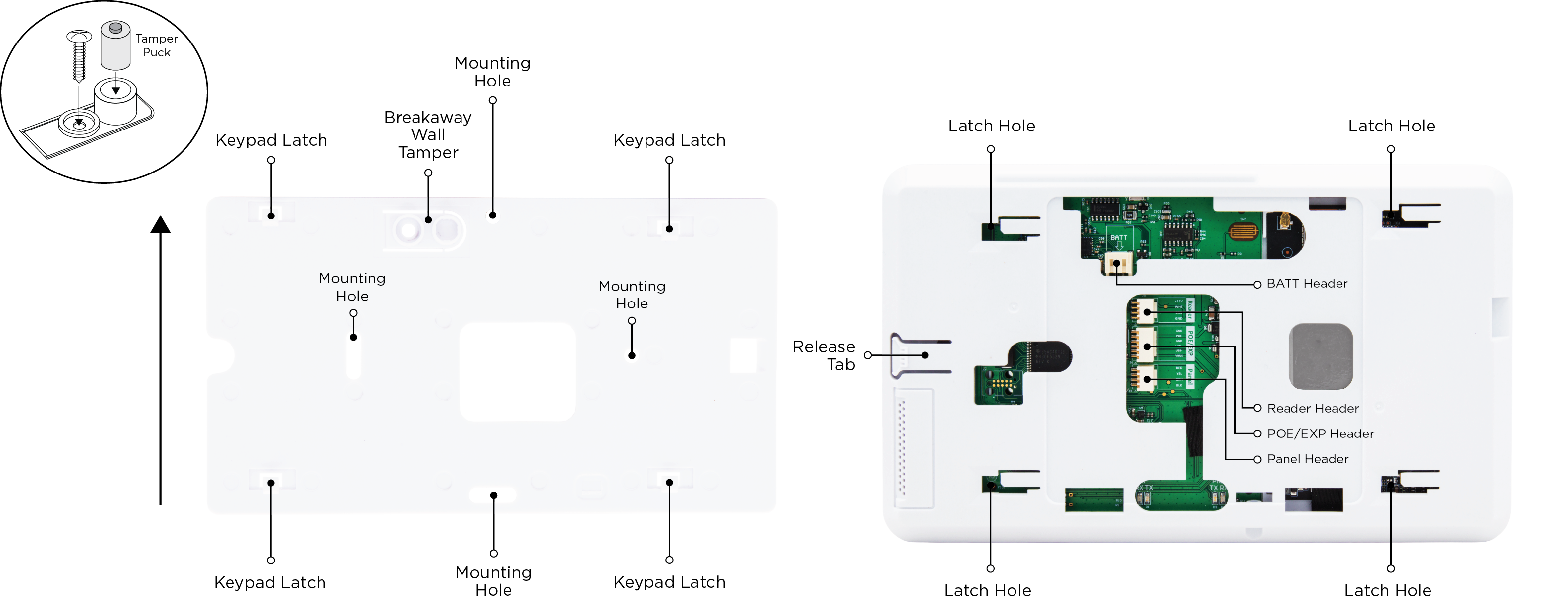
To mount a keypad using the mounting plate, refer to the figures and complete the following steps:
-
Place the keypad mounting plate against the wall at standing height to mark the holes for the mounting screws and tamper screw (if necessary). The breakaway wall tamper should be located at the top of the mounting plate, and the keypad latches should be facing up.
-
Set the base aside and drill the holes.
-
Use the screws included in the hardware pack to secure the keypad mounting plate to the wall.
-
Insert the tamper puck into the breakaway wall tamper.
-
Plug the 2- or 4-wire harness into the keypad PANEL header to connect it to the power source.
-
Ensure that the latch holes in the back of the keypad line up with the mounting plate keypad latches and that the on-board camera is on the left, then gently press the keypad to the mounting plate. Slide the keypad to the right until you hear the release tab on the side click to secure it onto the mounting plate.
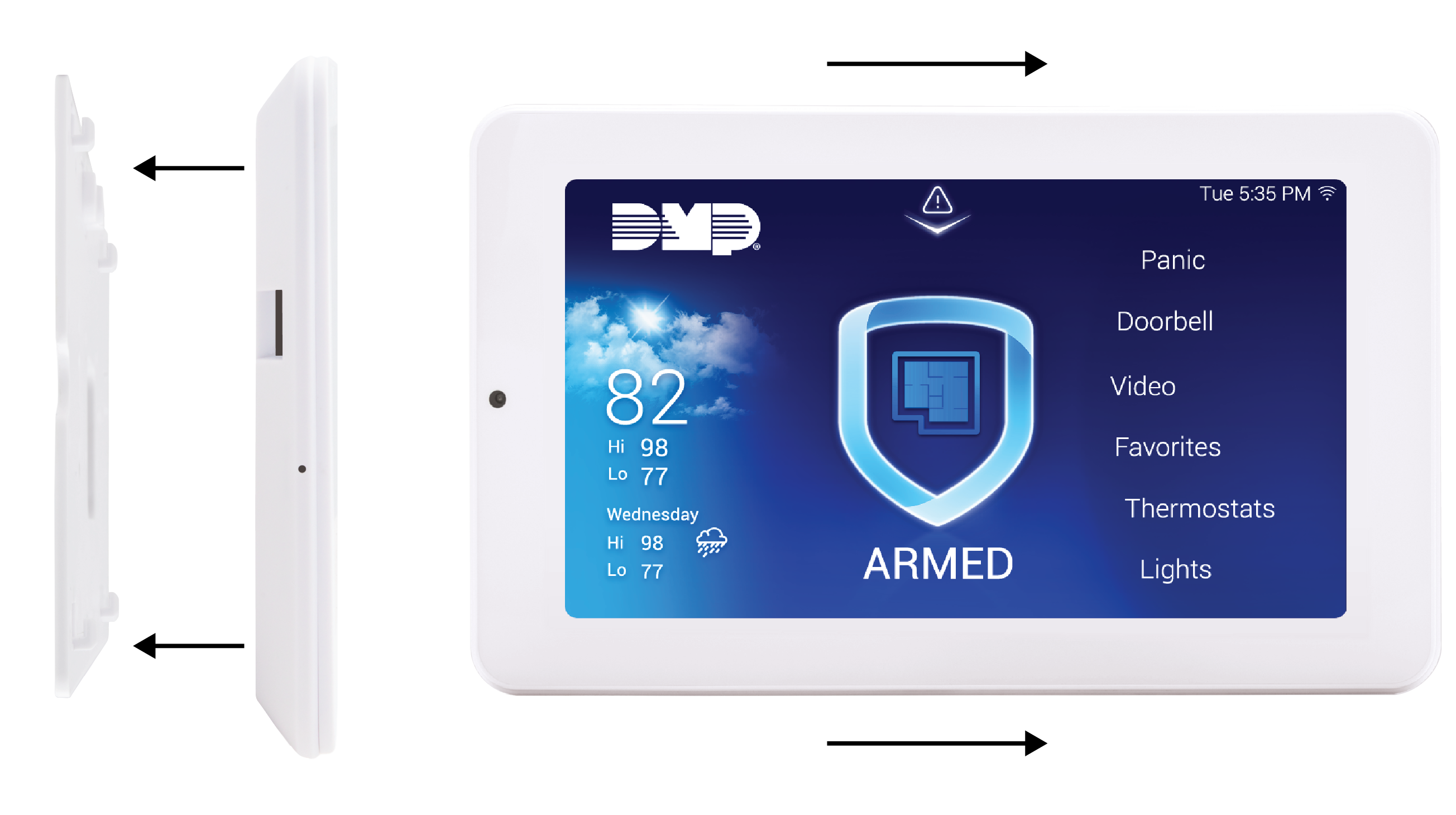
Removal
To remove the keypad from the mounting plate, locate the release tab on the right side of the keypad back and press down. This allows you to slide the keypad to the left and lift it away from the mounting plate.
Warning: Ensure that you slide the keypad to the side before pulling it away from the mounting plate. Failure to do so can result in damage to the keypad or mounting plate.
Desk Stand Mounting
Desk Stand Mounting
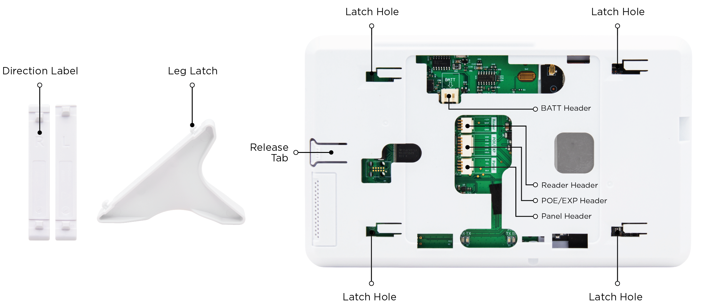
To mount a keypad using the desk stand, refer to the figures and complete the following steps:
-
Plug the 2- or 4-wire harness into the keypad PANEL header to connect it to the power source.
-
Locate the latch holes on the back of the keypad.
-
The desk stand legs are labeled L and R based on the keypad's front view and are not interchangeable due to latch spacing. Insert the desk stand leg marked with an L into the holes on the right side of the keypad, then slide it to the side to lock it in place. Repeat with the desk stand leg marked with an R on the left side of the keypad. The clear, non-slip rubber pads should be pointing down.
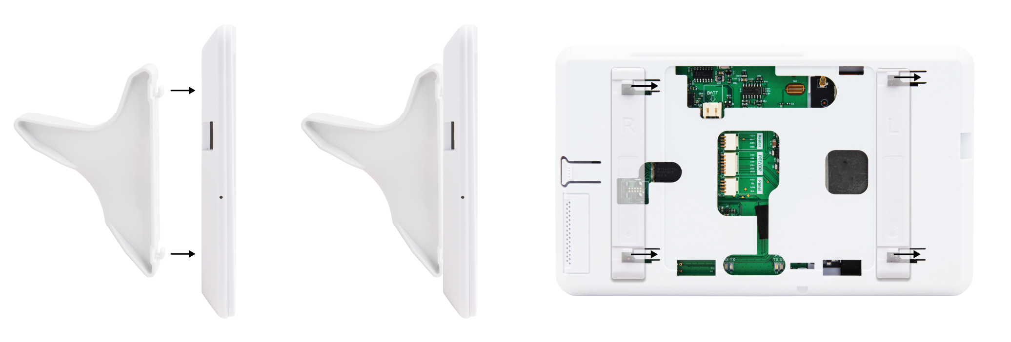
Removal
To remove the legs, slide them over and lift them from the holes.
Warning: Ensure that you slide the legs to the side before pulling them away from the keypad. Failure to do so can result in damage to the keypad or desk stand legs.
Wall Mounting with Optional Backup Battery
Wall Mounting
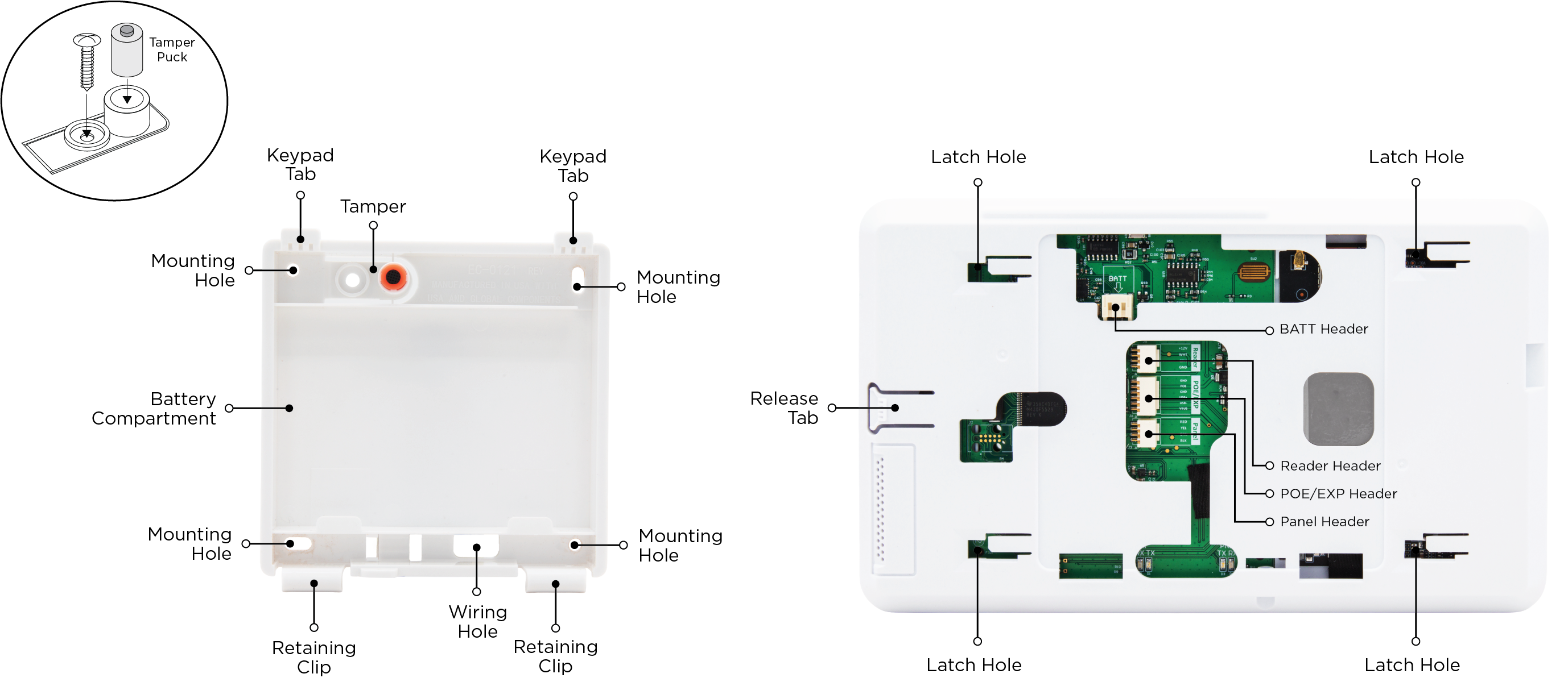
The backup battery case can act as a mounting device to install the keypad on a wall, so the included mounting plate is not necessary for this mounting process. To mount an 8863 which utilizes a backup battery on a wall, refer to the figures, and complete the following steps:
-
Place the battery case against the wall at standing height to mark the holes for the mounting screws and tamper screw (if necessary). The breakaway wall tamper should be at the top of the case.
-
Set the case aside and drill the holes.
-
Use the screws included in the hardware pack to secure the case to the wall. Insert the tamper puck into the case.
-
Pull the 2- or 4-wire harness through the wiring hole. Plug the harness into the PANEL header on the back of the 8863 to connect it to the power source.
-
Plug the battery into the BATT header on the back of the 8863, then place the battery into the case.
-
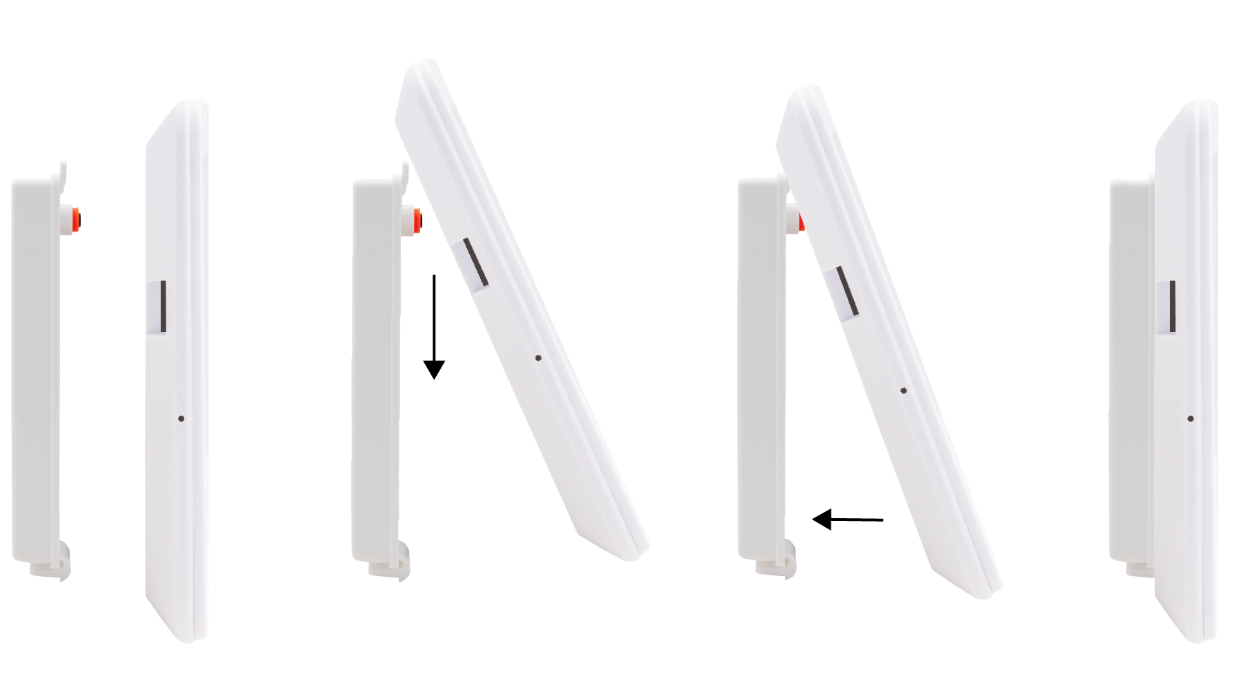
Slot the keypad tab holes over the tabs at the top of the battery case, then lower the keypad until it sits flush against the battery case.
-
Gently press the bottom of the keypad against the case until the retaining clips click into place.
Removal
To remove, press up on the retaining clips until they release. Support the battery while removing the keypad to prevent it from falling out of the battery case. Lift the bottom of the keypad away from the case and raise it straight up to remove the case tabs from the keypad tab holes.
Warning: Ensure that you have maneuvered the keypad up over the tabs and are supporting the battery before pulling it away from the battery case. Failure to do so can result in damage to the keypad, battery, or battery case.
Desk Stand Mounting with Optional Backup Battery
Desk Stand Mounting
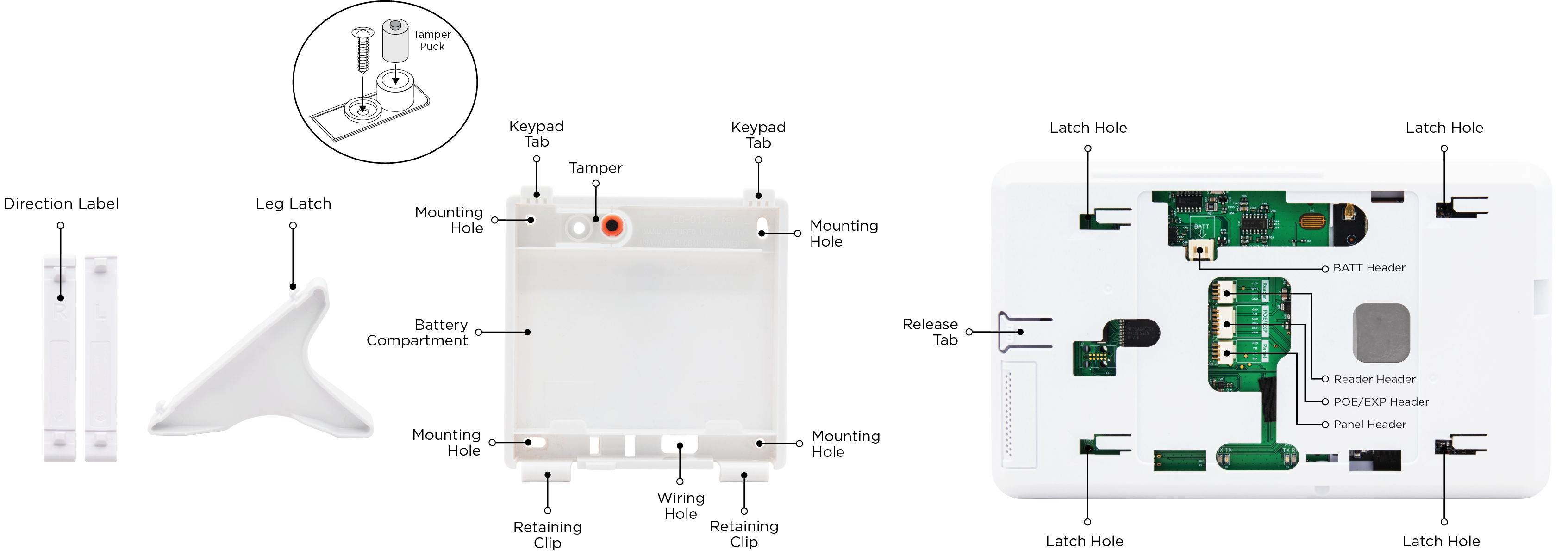
To mount an 8863 which utilizes a backup battery using the desk stand, refer to Figure X, and complete the following steps:
-
Plug the 2-or 4-wire harness into the PANEL header to connect it to the power source.
-
Plug the battery into the BATT header on the back of the 8863, then place the battery into the case.
-
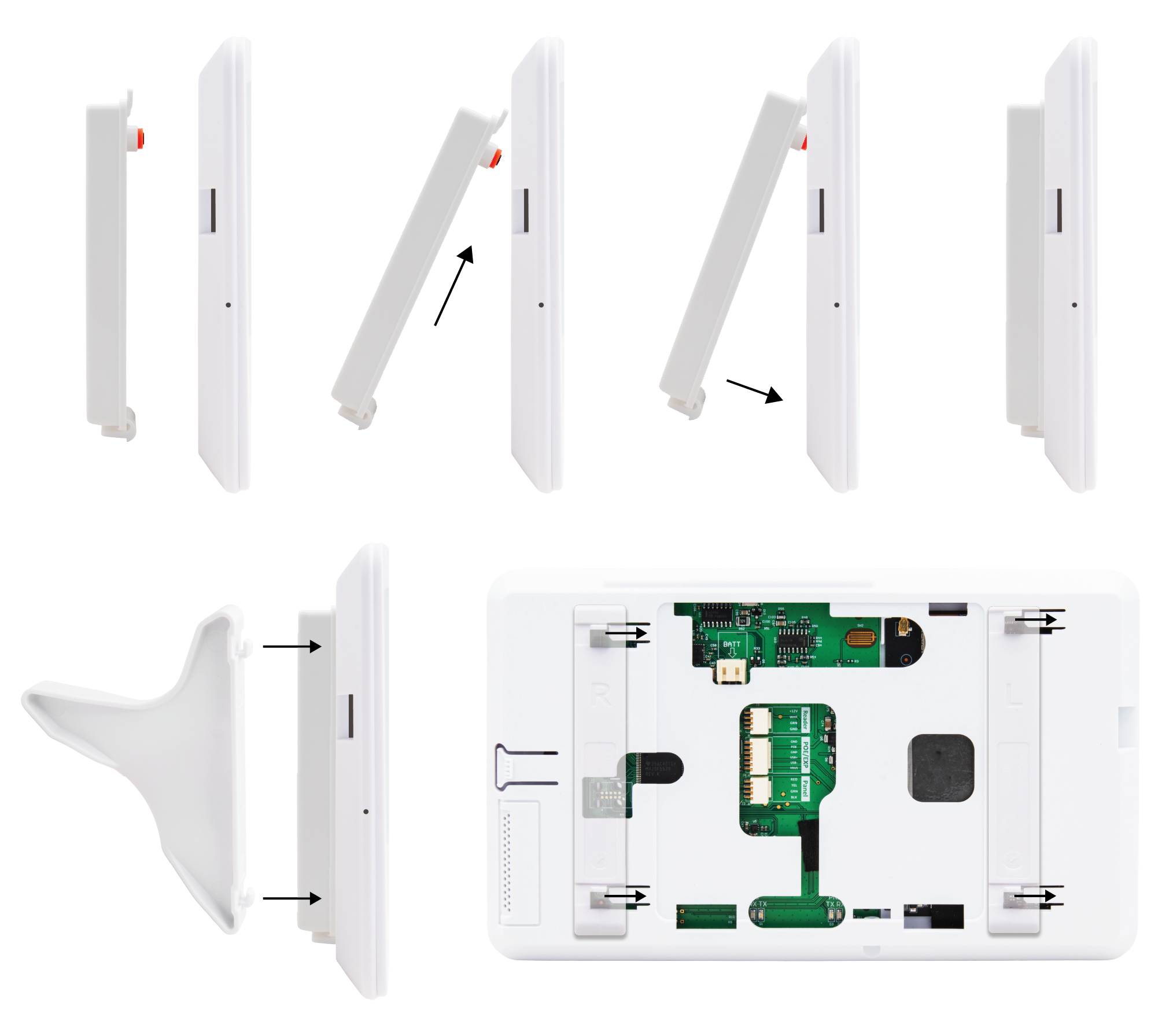
Insert the top tabs of the case into the keypad tab holes. The breakaway wall tamper should be at the top of the case. Lower the case until it sits flush against the back of the keypad.
-
Gently press the bottom of the case against the keypad until the retaining clips click into place.
-
Locate the latch holes on the back of the keypad.
-
The desk stand legs are labeled L and R based on the keypad's front view and are not interchangeable due to latch spacing. Insert the desk stand leg marked with an L into the holes on the right side of the keypad, then slide it to the side to lock it in place. Repeat with the desk stand leg marked with an R on the left side of the keypad. The clear, non-slip rubber pads should be pointing down.
Removal
To remove the legs, slide them over and lift them from the holes.
To remove the battery case, press up on the retaining clips until they release. Support the battery while removing the case to prevent it from falling. Lift the bottom of the case away from the keypad and pull down to remove the case tabs from the keypad tab holes.
Warning: Ensure that you slide the legs to the side before pulling them away from the keypad and confirm that you have maneuvered the keypad up over the tabs and are supporting the battery before pulling it away from the battery case. Failure to do so can result in damage to the keypad, battery, battery case, or desk stand legs.
5. Connect to Network
Connecting the keypad to Wi-Fi provides access to additional 8863 features, including remote updates, video system integration, personalized logos, and image capture when arming and disarming at the keypad. A Wi-Fi connection is recommended for all communication types to ensure access to these enhanced features.
To connect the keypad to Wi-Fi, complete the following:
-
Select Options from the Carousel menu.
-
Select Wi-Fi Settings.
-
Select the Wi-Fi network you would like to connect to.
-
Enter the password and select CMD.
6. Program the Keypad
Program the keypad to configure the communication settings.
-
Select Options in the Carousel Menu.
-
Select Installer Options, enter 3577 (INST), then press CMD.
-
Select Panel Communications.
-
Select Keypad Bus.
-
Enter the Keypad Address. It should match the Device Number set in Program the Panel.
7. Update the Keypad
To use the most up to date keypad features available, connect the keypad to Wi-Fi network and update to the latest firmware version. Follow the instructions for your chosen update method below.